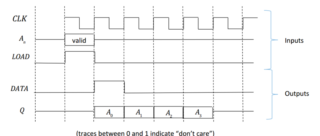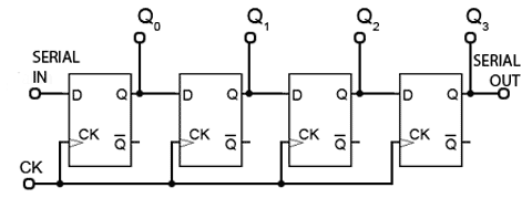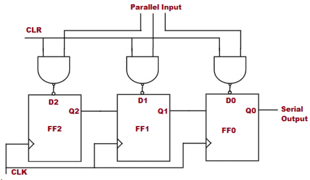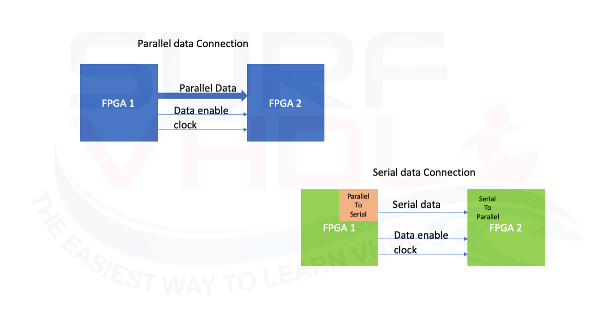

One register is used to clock in the serial stream, and the other is used to hold the data for the slower, parallel side. Implementations typically have two registers connected as a double buffer. The SIPO block then divides the incoming clock down to the parallel rate. However, SerDes which do not transmit a clock use reference clock to lock the PLL to the correct Tx frequency, avoiding low harmonic frequencies present in the data stream. The receive clock may have been recovered from the data by the serial clock recovery technique. The SIPO (Serial Input, Parallel Output) block typically has a receive clock output, a set of data output lines and output data latches. Implementations may also make use of a double-buffered register to avoid metastability when transferring data between clock domains. The simplest form of the PISO has a single shift register that receives the parallel data once per parallel clock, and shifts it out at the higher serial clock rate. It may use an internal or external phase-locked loop (PLL) to multiply the incoming parallel clock up to the serial frequency. The PISO (Parallel Input, Serial Output) block typically has a parallel clock input, a set of data input lines, and input data latches. There are 4 different SerDes architectures: (1) Parallel clock SerDes, (2) Embedded clock SerDes, (3) 8b/10b SerDes, (4) Bit interleaved SerDes. It does not store any personal data.The basic SerDes function is made up of two functional blocks: the Parallel In Serial Out (PISO) block (aka Parallel-to-Serial converter) and the Serial In Parallel Out (SIPO) block (aka Serial-to-Parallel converter). The cookie is set by the GDPR Cookie Consent plugin and is used to store whether or not user has consented to the use of cookies. The cookie is used to store the user consent for the cookies in the category "Performance". This cookie is set by GDPR Cookie Consent plugin. The cookie is used to store the user consent for the cookies in the category "Other. The cookies is used to store the user consent for the cookies in the category "Necessary".

The cookie is set by GDPR cookie consent to record the user consent for the cookies in the category "Functional". The cookie is used to store the user consent for the cookies in the category "Analytics". These cookies ensure basic functionalities and security features of the website, anonymously. Necessary cookies are absolutely essential for the website to function properly. The controller needs a 4 MHz ceramic resonator, X1. If there is a delay on the Centronics port, the RS232 bitstream from the computer may be stopped via the Flow signal (pin 17).

The IC also generates the requisite control signals. This is essentially a programmed PIC controller that produces a Centronics compatible signal from a 2400 baud serial signal (eight data bits, no parity, one stop bit). The serial-to-parallel conversion is effected by IC1. This is an integrated level converter that transforms the single +5V supply into a symmetrical ☑2V one. Since the computer needs real RS232 levels, an adaptation from TTL to RS232 is provided in the converter by a MAX232. The CTS and DSR signals enable handshaking to be implemented. The TxD line, pin 3, CTS line, pin 8 and the DSR line, pin 6, of the serial port are used – see diagram.

It converts a serial 2400 baud signal into a parallel signal. This converter may help if just the serial port on a personal computer is free, whereas the printer needs a parallel (Centronics) port.


 0 kommentar(er)
